
A good solar panel roof layout starts with orientation and tilt, but most UK installations are far more forgiving than people expect: systems within 30 degrees east or west of due south and between 15 and 50 degrees of tilt still generate about 95% of optimal yield (Sunsave, 2026). The bigger risk to a layout is usually shading and permitted development limits, not a few degrees of tilt.
This guide walks through solar panel layout design the way an installer actually plans it: orientation and tilt first, then row spacing to avoid winter self-shading, working around roof obstructions and multiple roof faces, panel orientation on the roof itself, and the permitted development rules that cap how a layout can look before it needs full planning permission.
Key Takeaways
- Orientation within 30 degrees of south and tilt between 15 and 50 degrees still captures roughly 95% of optimal annual yield.
- East or west facing roofs lose around 15% of output compared with due south, which is rarely a reason to abandon a roof face entirely.
- Pitched-roof panels are capped at 200mm protrusion above the roof slope and must not exceed the ridge height under permitted development.
- Row spacing calculations use the winter solstice sun angle, the worst-case shading condition, not an average or summer angle.
- Southern England systems typically see 1,050 to 1,100 kWh per kWp a year at optimal tilt, against 850 to 1,000 kWh per kWp further north.
What determines the best solar panel roof layout?
A solar panel roof layout comes down to four decisions in order: which roof face or faces to use, what tilt and orientation each panel gets, how far apart the rows sit to avoid self-shading, and how strings are split across faces with different orientations. Get the order wrong, particularly by fixing the panel count before checking shading, and the layout usually needs reworking once a proper survey happens.
Roof geometry drives most of the constraint. A simple single-pitch south-facing roof is the easiest layout problem in the trade, while a hipped roof with dormers, chimneys and roof lights turns into a puzzle of usable rectangles that rarely lines up with a round number of panels. Start the layout from the obstructions and usable area, not from a target kWp figure, and the panel count will follow naturally.
Orientation and tilt: how much do they actually matter?
Due south at 30 to 40 degrees tilt remains the reference point for maximum UK yield, but the tolerance either side is wide: anything within 30 degrees east or west of south, combined with a tilt between 15 and 50 degrees, still delivers around 95% of the optimal figure (Sunsave, 2026). Southeast and southwest roofs lose under 5% of output, while a true east or west-facing roof face loses closer to 15%.
That 15% loss on an east or west face is rarely a reason to skip it, especially on a roof with no usable south face at all, or where an east-west split spreads generation across more of the day rather than concentrating it around noon. Annual yield in southern England typically runs 1,050 to 1,100 kWh per kWp at optimal tilt, against roughly 850 to 1,000 kWh per kWp further north (Energy Saving Trust, 2026), so factor regional sun hours into the layout decision alongside orientation, not instead of it.
Orientation and tilt versus optimal yield
- Due south, 30-40° tilt: 100% reference yield.
- Southeast or southwest, 15-50° tilt: under 5% loss, roughly 95%+ of optimal.
- Within 30° east or west of south, 15-50° tilt: about 95% of optimal yield.
- Due east or due west, 15-50° tilt: around 15% loss, roughly 85% of optimal.
Source: Sunsave, 2026.
Row spacing and inter-row shading on pitched roofs
Row spacing calculations use the winter solstice sun angle, 21 December in the northern hemisphere, because that is when the sun sits lowest in the sky and shadows from a raised row stretch furthest across the row behind it. Spacing based on a summer or average sun angle will look fine for most of the year and then quietly lose output every winter for the system's entire life.
The core calculation is trigonometric: shadow length depends on panel tilt, row height and the sun's minimum elevation angle at the site's latitude, with sites further north needing wider spacing for the same tilt because the winter sun sits lower (SurgePV, 2026). On most single-pitch domestic roofs this is less of an issue than on flat commercial roofs with multiple rows, since a single roof face rarely has room for more than one physical row of panels running up the slope. Multi-row layouts on long pitched roofs or flat sections still need the same winter-angle check before committing to panel count.
Working around roof obstructions and multiple roof faces
Chimneys, roof lights, vents and party wall step-downs all cut into usable roof area, and a layout that ignores them on paper will not match what actually fits once an installer is on the roof with a tape measure. Map every obstruction from the survey, not from an aerial photo alone, since chimneys and vent stacks can be hard to judge accurately from satellite imagery, and get this wrong and the panel count promised in a quote will not fit on site.
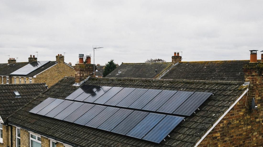
Splitting an array across two or more roof faces, for example a south-east and a south-west pitch either side of a ridge, means splitting strings to match, since panels on different faces see different irradiance through the day and should not share a single string with panels facing another direction. Two smaller strings on two orientations nearly always outperforms one string that ignores the mismatch, even though it adds a small amount of inverter or optimiser complexity to the design.
A hip roof with three or four usable faces multiplies this problem, since each face may need its own string or its own module-level optimiser if the roof geometry is complex enough. Walk the roof with the customer or from detailed imagery before quoting a panel count on a hipped or dormered property, because a number promised from a flat aerial view often shrinks once real obstruction clearances are marked out.
Portrait or landscape: does panel orientation matter?
Portrait orientation, panels mounted with the long edge vertical, is more common on UK pitched roofs because it usually fits roof width constraints better and can reduce the number of rows needed. Landscape orientation suits wider, shorter roof faces and can simplify cable runs to a single central point, but it is more sensitive to partial shading from a chimney or vent stack crossing a single row, since one shaded cell can affect a whole horizontal string of panels rather than a narrower vertical one.
Neither orientation has a meaningful yield advantage in clear conditions; the decision comes down to which one fits the roof's actual dimensions with the least wasted space and the fewest cut panels at the edges. Model both orientations against the real roof measurements before finalising a layout, particularly on an awkward roof shape where a few centimetres either way changes how many panels fit in a row.
Mixed orientation within a single roof face is rarely worth the added complexity, since it complicates rail runs and cable management for a marginal gain in panel count. Pick one orientation per face and only mix orientations between separate faces where the geometry genuinely demands it, such as a narrow dormer cheek that only fits panels one way round.
How does permitted development limit your layout options?
On a pitched roof, panels must not project more than 200mm from the roof slope and must not sit above the highest point of the roof, excluding the chimney, to qualify as permitted development (Planning Portal, 2026). On a flat roof, the highest point of the mounted equipment cannot exceed 600mm above the roof's highest point, and a standalone ground-mounted array is capped at 9 square metres, or 3 metres by 3 metres.
These limits shape layout more than most installers expect at quoting stage. A ballasted flat-roof mounting system tilted too steeply can breach the 600mm limit before it breaches any structural constraint, and a listed building or a conservation area with a highway-facing roof slope adds further restriction regardless of protrusion. Check planning permission constraints alongside the structural and shading survey, not after the layout is already drawn, since a permitted-development breach found late can force a full redesign.
Modelling tools and shading documentation
MCS documentation now expects a shading and yield estimate as standard evidence for every installation (MCS, 2026), which means a layout built on a rough compass-and-tilt guess will not satisfy the paperwork even if it happens to perform well on site. A proper 3D obstruction model, built from an accurate site survey rather than satellite imagery alone, catches the chimney and neighbour's-tree shading that a flat, top-down view misses entirely.
This matters more on roofs with any complexity at all, since a simple unshaded south roof rarely needs much modelling to get right, while a roof with a chimney breaking up one corner or an overshadowing tree on the boundary can lose several percentage points of annual yield to a layout that looked fine on paper. Tile-fixing method also feeds back into layout on a pitched roof: check BS 5534 compliance for the specific tile and fixing combination before finalising rail positions, since some fixing methods constrain where rails can sit relative to batten spacing.
How does layout change for in-roof or flat-roof systems?
In-roof mounted systems replace tiles rather than sitting above them, which removes the protrusion question entirely but constrains the layout to a rectangular block matching the replaced tile area, with less flexibility to work panels around an awkward obstruction than a standard on-roof mounting system offers. Flat roofs flip the layout problem again: instead of a fixed pitch and orientation set by the building, the installer chooses tilt and orientation within structural and ballast limits, which is why east-west flat-roof layouts, covered in detail for flat roof installations, can pack in more capacity than a south-only layout on the same footprint.
Whichever roof type, the layout decision sequence stays the same: obstructions and usable area first, orientation and tilt second, row spacing and string splitting last. Reonic's platform helps installers turn a site survey into a documented layout and yield estimate without re-running the trigonometry by hand on every job.
FAQ
What is the best orientation for a solar panel roof layout in the UK?
Due south at 30 to 40 degrees tilt gives the maximum yield, but anything within 30 degrees east or west of south and a tilt between 15 and 50 degrees still captures about 95% of that optimal output. Shading is usually a bigger factor in final yield than a few degrees of orientation.
How much roof area can solar panels cover under permitted development?
Permitted development rules focus on protrusion and height rather than a fixed percentage of roof area: pitched-roof panels must sit within 200mm of the roof slope and below the ridge, while flat-roof equipment is capped at 600mm above the roof's highest point. Check current local authority guidance for any area-specific conditions.
Why does row spacing use the winter sun angle instead of summer?
The winter solstice produces the sun's lowest elevation angle, which casts the longest shadows from any raised row. Spacing calculated for a higher summer sun angle would look adequate most of the year but cause avoidable self-shading losses every winter for the life of the system.
Does portrait or landscape panel orientation generate more electricity?
Neither orientation has a meaningful yield advantage under clear skies. The choice comes down to which orientation fits the roof's actual dimensions with less wasted space, and landscape strings are more exposed to a single shading source affecting the whole row.
Do I need a 3D shading model for a simple roof layout?
A simple, unobstructed south-facing roof rarely needs extensive modelling, but MCS documentation now expects a shading and yield estimate as standard evidence for every installation. Any roof with a chimney, roof light or nearby tree benefits from a proper 3D obstruction model rather than a compass-and-tilt estimate alone.
Related guide: after layout and install, see our solar panel maintenance guide.