
A G99 relay is the interface protection device that disconnects a generator or battery from the grid when voltage, frequency or the rate of change of frequency drifts outside safe limits, and the current rulebook for it is EREC G99 Issue 2, published by the Energy Networks Association on 10 March 2025 (ENA, 2025). For UK solar and storage installers, getting the relay right is the difference between a witness test that passes first time and a job that stalls at the Distribution Network Operator.
This guide covers what the relay actually protects against, when the DNO insists on one, the interface protection settings the network expects to see, and the storage changes that take effect on 1 March 2026. The perspective is installer-first: what you specify, wire and demonstrate on site, not the transmission-scale theory.
Key Takeaways
- A G99 relay provides interface protection: it trips the connection on under/over voltage, under/over frequency and loss of mains, protecting both the network and your plant.
- Loss-of-mains detection now uses a rate-of-change-of-frequency setting of 1.0 Hz/s, replacing the older, trip-happy 0.125 Hz/s value from the ALoMCP programme.
- You can use type-tested protection, where settings are fixed in the factory and logged on the ENA register, or non-type-tested protection, which you must prove on site.
Protection settings only mean something next to the string design and the circuit plan they protect. See how all-in-one solar software keeps the two on the same job.
- EREC G99 Issue 2 (10 March 2025) adds mandatory requirements for generating modules with electricity storage that come into force on 1 March 2026.
- Always match the relay settings to the protection settings schedule in your DNO connection offer, not to a generic default.
What is a G99 relay and what does it do?
A G99 relay is an interface protection device that continuously watches the grid supply and decouples your generator or battery the instant conditions leave the permitted envelope. Any system running parallel to the mains must include a relay that can initiate disconnection if a fault develops on either side (G99 Training, 2025). It protects the network from being back-fed and protects your inverter or plant from damage.
The relay monitors four core quantities: voltage, frequency, rate of change of frequency, and in some cases vector shift. When a measured value crosses a threshold for longer than the set time delay, the relay opens a contactor and takes the installation offline. This is why the DNO treats the relay, not the inverter alone, as the compliance boundary of the connection.
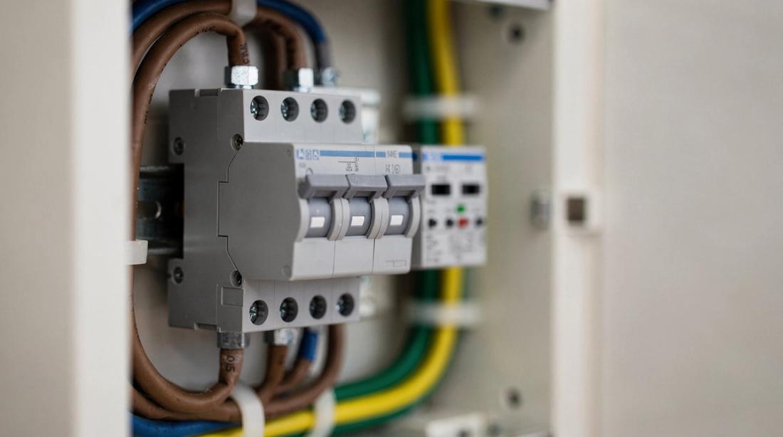
Physically, interface protection can live in one of two places. On most modern domestic systems it sits inside the inverter as firmware, tested and declared by the manufacturer. On larger or multi-inverter sites it is a discrete relay wired to a dedicated tripping contactor at the point of connection. Knowing which arrangement your job uses decides whether you are configuring a menu or wiring and testing a separate device, and it shapes the evidence the DNO expects to see in the single line diagram.
When does the DNO require a G99 relay?
The DNO requires G99 interface protection whenever a connection exceeds the G98 limit of 16 A per phase, which is roughly 3.68 kW single phase or 11 kW three phase, or when you connect before receiving approval. Below that, most inverter-only microgeneration falls under G98 connect-and-notify (Reonic G98 guide, 2026). Above it you need G99 pre-approval and the protection the DNO specifies.
Smaller type-tested inverters often carry their interface protection internally, so a separate external relay is not always needed. Larger systems, multiple inverters, or connections where the DNO asks for evidence in the single line diagram usually need a dedicated external relay. The G99 application process and DNO offer confirm exactly what is required (Reonic G99 guide, 2026).
G99 interface protection settings explained
G99 interface protection settings define the voltage and frequency window inside which your system must stay connected, and the trip points beyond it. The operating envelope requires continuous connection between roughly 85% and 110% of nominal voltage and between 47.5 Hz and 51.5 Hz, with fast trips outside that (ENA, 2025). The table below shows the typical default shape; the exact figures always come from your DNO schedule.
- Under-voltage: trips below about 87% of nominal, with a short delay confirmed in the DNO schedule.
- Over-voltage: trips above about 110% of nominal on a 10-minute average, with a faster stage near 114%.
- Under-frequency: stage one near 47.5 Hz with a delay of roughly 20 seconds, fast stage near 47 Hz.
- Over-frequency: stage one near 51.5 Hz with a delay, fast stage near 52 Hz.
- Rate of change of frequency (loss of mains): 1.0 Hz/s with a definite time delay of about 0.5 seconds (Carter Sullivan, 2025).
- Vector shift: commonly disabled under current ENA guidance to reduce nuisance tripping.
Treat these as the shape of the settings, not the settings themselves. The DNO can specify modified voltage trip points for a particular connection point based on local network conditions, and the witness test checks the relay against that schedule, not against a textbook.
Type-tested or non-type-tested protection: which do you need?
G99 permits two routes. Type-tested interface protection has its settings fixed during manufacture and the design is logged on the ENA Type Test Verification Report Register, so the DNO accepts it on paper (G99 Training, 2025). Non-type-tested protection is allowed but you must test and measure on site to prove every setting meets G99.
For most domestic and small commercial jobs, a type-tested relay or a type-tested inverter is the path of least resistance, because it removes an on-site verification burden. A Type A synchronous module at or below 50 kW can often be signed off using the manufacturer declaration on Form A2-1 (ENA, 2025). Non-type-tested kit tends to appear on bespoke or legacy installations.
Loss of mains protection: ROCOF and vector shift explained
Loss of mains protection detects when the grid supply disappears but the generator keeps running, which would create a dangerous island that can back-feed an isolated section of network. G99 relies mainly on rate of change of frequency for this, set at 1.0 Hz/s (PSC Consulting, 2025). It is the one requirement that clearly separates G99 from the simpler G98 regime, and it is the setting DNOs scrutinise most closely.
The 1.0 Hz/s value is itself the result of the Accelerated Loss of Mains Change Programme, which raised the threshold from the older 0.125 Hz/s setting that was tripping systems on normal grid transients (G99 Testing, 2025). Vector shift was historically used too, but current guidance leans on ROCOF and often disables vector shift to cut false trips. A field point worth remembering: on sites with weak or long supply cables, even a correctly set relay can nuisance trip, so record the network impedance during the survey and flag it to the DNO rather than quietly widening the settings yourself.
What changed in EREC G99 Issue 2 for 2026?
EREC G99 Issue 2 was published on 10 March 2025 and introduces new mandatory requirements for power generating modules that incorporate electricity storage, which come into force on 1 March 2026 (ENA, 2025). For battery installers this is the headline change: storage-specific behaviour is now written into the protection and compliance rules rather than treated as an add-on.
If you install AC-coupled or hybrid battery systems, confirm that your inverter and relay firmware are declared against Issue 2, and that any export limitation interacts correctly with the interface protection (Reonic G100 guide, 2026). Kit certified only against earlier issues may need a firmware or documentation update before a 2026 connection is accepted.
How do you commission and witness-test a G99 relay?
Commissioning a G99 relay means injecting test signals to prove each protection stage trips at the set threshold within the set time, then recording the results for the DNO. For non-type-tested protection, ROCOF and vector shift stability testing must be carried out on every interface protection relay, whether type tested or not (Carter Sullivan, 2025).
The DNO may attend a witness test for larger connections, so book it early and bring the protection settings schedule, the relay test sheets and the single line diagram (Reonic SLD guide, 2026). Documenting the as-tested settings is what converts a wired relay into an approved connection.
Common G99 relay mistakes installers make
The most frequent error is using generic factory defaults instead of the values in the DNO offer, which fails the witness test on the day. Others include leaving vector shift enabled when the schedule disables it, wiring the trip contactor so it fails unsafe, and specifying a relay certified only to an old G99 issue for a system that connects in 2026.
A practical check before you leave site: read back the live settings from the relay, photograph the display, and file them against the DNO schedule. On battery jobs, verify the interface protection still behaves correctly when the system switches between charge and export, because that transition is where storage-specific faults tend to surface. Reonic's platform helps installers keep these compliance records tied to each job so nothing is lost between survey and sign-off.
Do I need a G99 relay for a small solar system?
Not always. Systems at or below 16 A per phase, about 3.68 kW single phase, connect under G98 and usually rely on the inverter's built-in protection. Above that limit, or where the DNO asks for external evidence, you need G99 interface protection, which may be a type-tested inverter or a separate relay.
What is the ROCOF setting for a G99 relay?
The current standard rate-of-change-of-frequency setting for loss-of-mains protection is 1.0 Hz/s with a definite time delay of around 0.5 seconds. This replaced the older 0.125 Hz/s value under the Accelerated Loss of Mains Change Programme, because the lower threshold was tripping systems on normal grid disturbances.
Is vector shift still required under G99?
Vector shift is part of the G99 toolkit but current ENA guidance commonly disables it in favour of rate-of-change-of-frequency detection, because vector shift caused nuisance trips. Always follow the protection settings schedule in your DNO offer, which states explicitly whether vector shift should be enabled or removed for your connection.
What is the difference between type-tested and non-type-tested protection?
Type-tested protection has its settings fixed at manufacture and is logged on the ENA register, so the DNO accepts it without on-site verification of the design. Non-type-tested protection is permitted but you must test and measure each setting on site to demonstrate it meets every G99 requirement, which adds commissioning time.
When do the 2026 G99 storage rules apply?
EREC G99 Issue 2, published on 10 March 2025, adds mandatory requirements for generating modules incorporating electricity storage that take effect on 1 March 2026. Battery and hybrid installers should confirm inverter and relay firmware are declared against Issue 2 before any connection that completes on or after that date.