

What is the Single-Line Diagram and Why It Is Essential
The single-line diagram represents the most important graphical document in professional electrical design in Italy. This technical drawing summarizes the entire architecture of an electrical system through a simplified yet complete representation, using a single line to represent circuits that may contain multiple conductors in reality.
Technical Definition of the Single-Line Diagram
In professional contexts, the single-line diagram is a standardized graphical representation that shows all electrical equipment, cables, protective devices, distribution lines, and main connections of the system. Each component is represented using standardized technical symbols according to CEI (Italian Electrotechnical Committee) and IEC (International Electrotechnical Commission) standards.
The distinctive characteristic of this type of diagram is its ability to represent complex circuits using a single graphical line, drastically simplifying the understanding of the electrical network without losing essential technical information.
Application Areas in Modern Electrical Systems
Single-line diagrams find application in multiple contexts:
- Residential civil installations: apartments, villas, condominiums
- Industrial installations: production facilities, warehouses, industrial buildings
- Commercial installations: shops, shopping centers, offices
- Special installations: photovoltaic, home automation, security systems, UPS
- Public installations: schools, hospitals, sports facilities
Why the Diagram is Essential for Electrical Safety
The single-line diagram is not simply a mandatory technical drawing: it represents the fundamental tool for ensuring safety, efficiency, and regulatory compliance of any electrical installation.
Simplification of Complex Circuits
The single-line representation allows designers to compress complex technical information into an immediately readable layout. Instead of drawing all conductors separately (as in multi-line diagrams), a single line is used accompanied by annotations specifying the number and type of conductors present.
This simplification is particularly valuable in large industrial installations, where hundreds of circuits must be coordinated and documented clearly.
Prevention of Design and Installation Errors
Confused or unclear design can generate:
- Unexpected additional costs during installation
- Significant delays in completion times
- Electrical risks from overloads or inadequate protections
- Regulatory non-compliance with resulting penalties
The single-line diagram allows rapid identification of logical errors, potential overloads, missing differential protections, or inadequate coordination between protective devices before the system is built.
Effective Communication Between Professionals and Clients
The document facilitates communication between different professional figures:
- Electrical designers: use the diagram to size the system
- Installers: follow the diagram to physically build the system
- Inspectors: check regulatory compliance
- Maintenance technicians: intervene quickly in case of failures
- End clients: understand the general structure of their system
This communicative clarity reduces misunderstandings and ensures that all actors involved have a shared vision of the project.
Main Components of the Single-Line Diagram
A complete single-line diagram contains a series of fundamental elements that allow immediate understanding of the entire electrical architecture. Each component follows standardized symbology to ensure universal consistency.
Power Supply and Distribution Lines
Power supply lines represent the path of electrical energy from the main source (meter, transformer substation) to the terminal circuits. In single-line representation, a single line can contain multiple actual conductors: phases, neutral, and protective conductor (earth).
Each line must be accompanied by essential technical information:
- Cable cross-section (e.g., 2.5 mm², 4 mm², 6 mm²)
- Rated capacity in amperes
- Conductor material (copper or aluminum)
- Installation method (concealed, in conduit, on cable tray)
- Number of conductors (e.g., 3x2.5 mm² + E means three 2.5 mm² conductors plus earth)
- Insulation type
These specifications ensure that each circuit is designed to safely support the expected load in compliance with technical standards.
Magnetothermal and Differential Circuit Breakers
Protective devices represent the heart of electrical system safety. The single-line diagram must clearly indicate:
Magnetothermal circuit breakers: protect against overloads and short circuits. For each, the following must be specified:
- Rated current (In): for example 10A, 16A, 20A, 32A
- Breaking capacity (Icu or Icn): ability to interrupt high fault currents (e.g., 6kA, 10kA)
- Trip curve: type B (for resistive loads), C (general use), D (motors and inductive loads)
- Number of poles: 1P, 1P+N, 2P, 3P, 4P
Residual current devices (RCDs): monitor current leakage to earth. Characteristics to indicate:
- Trip sensitivity: 10 mA (bathrooms), 30 mA (general use), 300 mA or 1A (fire protection)
- Type: AC (linear loads), A (electronic presence), B (inverters and UPS)
- Trip time: instantaneous or delayed (for selectivity)
Accurate documentation of these protections ensures operational reliability and simplifies future maintenance interventions.
Standardized CEI and IEC Electrical Symbols
The symbology used in Italian single-line diagrams strictly follows CEI (Italian Electrotechnical Committee) and IEC (International Electrotechnical Commission) standards. The most common symbols include:
- Electrical outlets: different for domestic, industrial, CEE use
- Electrical panels: main, secondary, zone
- Terminal blocks and junction boxes
- Lamps and lighting fixtures
- Relays and contactors
- Transformers and autotransformers
- Earthing systems: earth electrode, main earthing terminal
- Disconnecting devices
- Measuring instruments: voltmeters, ammeters, energy meters
The use of standardized symbology eliminates incorrect interpretations during installation, maintenance, or subsequent modifications and expansions of the system.
Italian Reference Standards for the Single-Line Diagram
Electrical design in Italy is regulated by precise technical standards that ensure safety, quality, and complete traceability of installations. The single-line diagram must strictly comply with these regulatory standards.
CEI 0-2 Standard: Documentation of Electrical Projects
The CEI 0-2 standard governs the guide for defining electrical installation project documentation. This standard specifies:
- Which technical documents must be mandatorily produced
- How electrical symbols must be graphically represented
- What level of detail is required based on the type and complexity of the installation
- The criteria for archiving and updating documentation
The single-line diagram is among the fundamental and mandatory documents for any professional electrical project, regardless of the installation size.
CEI 64-8 Standard: User Electrical Installations
The CEI 64-8 represents the cornerstone standard for the design, execution, and verification of user electrical installations at nominal voltage not exceeding 1000 V AC and 1500 V DC.
This standard indicates the fundamental minimum requirements for:
- Protection against direct and indirect contact
- Disconnection and control of the installation
- Efficient energy distribution
- Selection and sizing of equipment
- Protection against overcurrents and overvoltages
- Coordination of protections
The single-line diagram must clearly demonstrate that all these regulatory requirements have been met in the design, providing documentary evidence of compliance.
Mandatory Documentation According to DM 37/08
According to Italian regulations (Ministerial Decree 37/2008 regulating installation safety), the following must always be produced and preserved:
- Single-line diagram of the main electrical panel
- Single-line diagrams of secondary and distribution panels
- Floor plans with conduit routes and cable paths
- Technical design report
- Declaration of conformity issued by the installer
- Certifications of materials used
The absence of this documentation results in administrative penalties and the impossibility of obtaining occupancy or habitability certificates.
How to Read a Single-Line Diagram Correctly
Knowing how to interpret a single-line diagram is an essential skill for anyone working in the electrical sector, from installers to designers, from maintenance technicians to construction managers.
Recognition of Standardized Symbols
The first fundamental step consists of correctly interpreting the graphical symbols. Each electrical element is represented with a precise and universally recognized shape according to CEI standards.
A complete legend inserted directly in the diagram or in an attached document facilitates the decoding of any special or customized symbols used by the designer for specific installation needs.
Tracing the Energy Flow
The single-line diagram visually shows the flow of electrical energy from the power source (utility meter, MV/LV substation, generator) to the final loads (outlets, lamps, motors, machinery).
Following this logical path, one can identify:
- Protections present along each circuit branch
- Coordination and selectivity between different protections
- Potential critical nodes or points of energy congestion
- Connected loads and their distribution across phases
- Alternative paths in case of redundant power supplies
Detailed Analysis of Electrical Panels
Each electrical panel (main, secondary, zone) is represented through a hierarchical modular structure. The qualified technician must verify:
- Adequate sizing of all installed devices
- Vertical selectivity between upstream and downstream protections
- Load balance between the three phases (in three-phase installations)
- Logical subdivision of circuits by function or served area
- Presence of spare capacity for future expansions
How to Create a Professional Single-Line Diagram
Creating a compliant and professional single-line diagram requires in-depth technical skills, up-to-date knowledge of regulations, and the use of appropriate software tools.
Choosing Professional Software
Modern design is based on dedicated software that ensures precision, regulatory compliance, and ease of updating. The main tools used in Italy are:
AutoCAD Electrical: specialized version of AutoCAD for electrical drawings, offers libraries of standardized symbols and specific functions for electrical diagrams. Ideal for advanced customizations.
SPAC Automazione: Italian software widely used among national designers, includes complete CEI-compliant libraries, automatic voltage drop calculations, and protection sizing.
EPLAN Electric P8: high-end international professional standard, used especially in industrial settings for complex installations. Allows complete management of design documentation.
SEE Electrical: French alternative highly appreciated for its good quality-price ratio and intuitive interface.
These tools allow the creation of precise diagrams, easily updatable and perfectly integrable with other parts of the project (floor plans, bills of quantities, specifications).
Optimal Design Sequence and Methodology
A well-designed single-line diagram must follow a structured design methodology:
- Accurate definition of electrical loads: complete inventory of all users with absorbed power
- Selection of protective devices: sizing of magnetothermal and differential devices based on loads
- Creation of panel hierarchy: definition of main panel and secondary panels
- Calculation of cable cross-sections: based on current-carrying capacity, voltage drop, and installation method
- Clear graphical representation: correct use of standardized symbols
- Verification of regulatory compliance: checking against CEI 64-8 and other applicable standards
- Final review and optimization: error elimination and readability improvement
Common Errors to Absolutely Avoid
Among the most frequent errors in drafting single-line diagrams are:
- Incorrect or non-standardized use of electrical symbols
- Absence of fundamental technical data (rated currents, cable cross-sections)
- Poor graphical readability of the drawing (symbols too small, confused lines)
- Inconsistency between design diagram and installed reality
- Failure to indicate differential protections
- Absence of explanatory legend
- Lack of protection coordination
Practical Examples of Single-Line Diagrams
Residential Civil Electrical Installation
A single-line diagram for a typical residential dwelling includes:
- Main electrical panel with main circuit breaker
- Magnetothermal circuit breakers dedicated for lighting and outlets
- 30 mA differential circuit breakers for personal protection
- Dedicated and protected lines for kitchen (oven, dishwasher)
- Dedicated lines for bathrooms with reinforced differential protection
- Possible separate line for air conditioners or heat pumps
Although relatively simple, it must still strictly comply with all CEI 64-8 regulatory requirements, particularly regarding protections in wet locations.
Industrial Electrical Installation
In production contexts, the single-line diagram becomes significantly more complex and articulated:
- Multiple distribution panels organized hierarchically
- Electric motor starters with dedicated thermal protections
- Specialized protection relays (phase loss, phase sequence, undervoltage)
- UPS systems and continuity groups for critical loads
- Centralized or distributed power factor correction
- Supervision and control systems (SCADA, PLC)
Grid-Connected Photovoltaic Installation
A photovoltaic installation requires specific representation of:
- Photovoltaic module strings with electrical characteristics
- DC/AC conversion inverters with rated power
- DC-side protection devices: disconnectors, surge arresters
- AC-side protection devices: interface protections according to CEI 0-21
- Energy monitoring systems
- Connection point to the existing electrical grid
Single-Line Diagram Example
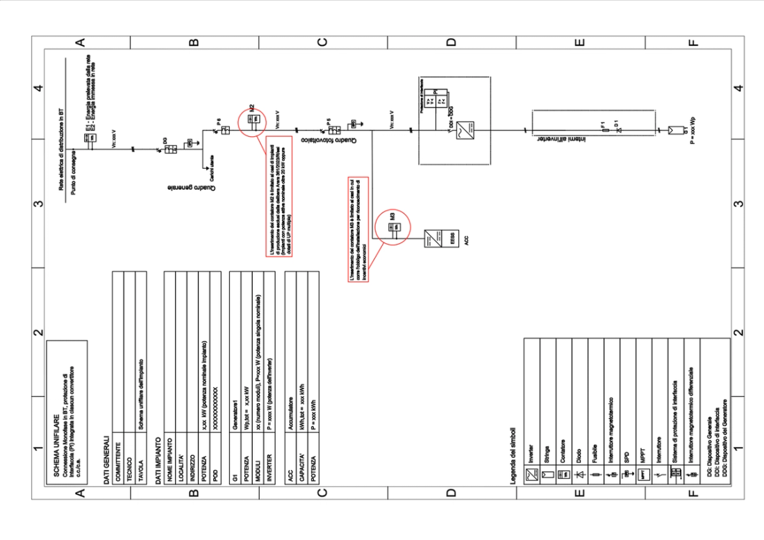
Standard single-line diagram for single-phase low-voltage installations equipped with storage system and battery on the AC (alternating current) production side
Advantages of Single-Line Diagram Compared to Multi-Line Diagram
Comparison Between the Two Types of Representation
The single-line diagram simplifies representation by using a single line to indicate the electrical path, regardless of the actual number of conductors present. It is concise, immediate, ideal for overall vision.
The multi-line diagram instead represents each individual conductor with a separate line, showing all point-to-point connections in detail. It is complex but comprehensive.
When to Use Each Type
Single-line diagram: ideal for general design, official documentation, client presentation, connection requests, authorization procedures.
Multi-line diagram: necessary for complex wiring in electrical panels, industrial automation diagrams, PLC control connections, home automation installations with communication bus.
In many professional projects, both are used: the single-line for overall vision and multi-line for construction details of individual panels.
Tools and Resources for Creating Single-Line Diagrams
Free Software to Get Started
QElectroTech: open-source cross-platform software, includes libraries of electrical symbols and allows creation of good quality diagrams.
TinyCAD: free program for Windows, simple to use for small-scale projects.
Professional Electrical Symbol Libraries
Valuable resources available on:
- Official CEI website (https://www.ceiweb.it): updated standards and symbols
- Manufacturer portals: ABB, Schneider Electric, Siemens offer free CAD libraries
- Designer communities: specialized forums with shared templates
Continuing Professional Education
To stay updated on regulations:
- CEI professional update courses
- Technical webinars organized by electrical equipment manufacturers
- Industry conferences and trade fairs (Elettroexpo, SPS Italia)
Conclusions: The Strategic Importance of the Single-Line Diagram
The single-line diagram represents much more than a simple regulatory obligation: it is the fundamental strategic tool for electrical designers, qualified installers, and maintenance technicians who wish to create safe, efficient, orderly installations that fully comply with strict Italian regulations.
Proper graphical representation allows prevention of costly errors, dramatic improvement of routine and extraordinary maintenance efficiency, guarantee of reliable and professional energy distribution, facilitation of future expansions, and demonstration of regulatory compliance during inspections.
Investing time and skills in the accurate creation of the single-line diagram means significantly increasing the overall quality of the entire electrical installation, protecting people's safety, and preserving the economic value of the investment over time.
Mastery of this design tool, combined with in-depth knowledge of CEI standards and the use of updated professional software, distinguishes the competent professional from those who improvise, ensuring excellent and lasting results over time.
Frequently Asked Questions About the Single-Line Diagram
1. What exactly is a single-line diagram used for?
It is used to represent in a simplified yet complete manner the entire architecture of an electrical system, showing protections, distribution lines, loads, and safety devices.
2. Is the single-line diagram legally required in Italy?
Yes, it is mandatory according to DM 37/08 for all new, modified, or expanded electrical installations. It is part of the compliance documentation.
3. Can I create it without professional software?
Technically yes, even manually or with free software, but dedicated programs ensure greater precision, regulatory compliance, and ease of modification.
4. Does the single-line diagram also show the physical cable routes?
No, it shows electrical connections in simplified logical form. Physical routes are represented in installation floor plans.
5. How detailed should a single-line diagram be?
It must always include all protections, characteristics of main lines, significant loads, and essential technical data. The level of detail increases with the complexity of the installation.
6. Is it also necessary for photovoltaic installations?
Absolutely yes. It is mandatory for all PV installations connected to the electrical grid and must comply with CEI 0-21 standard for connections.
7. Who can sign a single-line diagram?
It must be signed by a qualified professional: electrical engineer, industrial electrical technician, or equivalent professional figure registered with the professional board.
8. How often should it be updated?
It must be updated every time substantial modifications are made to the electrical installation, to maintain correspondence between documentation and installed reality.
What is the Single-Line Diagram and Why It Is Essential
The single-line diagram is the most important graphical document in professional electrical design in Italy. This technical drawing summarizes the entire architecture of an electrical system through a simplified yet complete representation, using a single line to represent circuits that may contain multiple conductors in reality.