
EV charger load management keeps a charge point inside the limit of the incoming supply, and it matters because a typical UK home has only a 100A single-phase main fuse while a 7.4kW charger already draws about 32A (RW Currion Electrical, 2026). Add a cooker and a shower and the fuse is at risk.
This guide answers the questions installers ask about load management: what it is, how a CT clamp controls the charger, static versus dynamic balancing, how much extra capacity you gain, what three-phase and commercial sites need, and what BS 7671 and the Smart Charge Point Regulations demand at commissioning.
Key Takeaways
- A 7.4kW charger draws roughly 32A against a 100A main fuse, so load management stops the total site current tripping the supply (RW Currion Electrical, 2026).
- A CT clamp on the meter tails lets the charger see total demand in real time and throttle its output before the fuse is stressed (Squote, 2026).
- Dynamic load management can free 30% to 50% more charging capacity inside the same supply than a fixed static limit (Nuvolt, 2026).
- A compliant smart-charger install usually needs a Type B RCD to meet the BS 7671 18th Edition wiring regulations (EcoHarmony, 2026).
- Domestic charge points must default to off-peak charging with a random delay of up to 600 seconds under the Smart Charge Point Regulations (legislation.gov.uk, 2026).
What is EV charger load management?
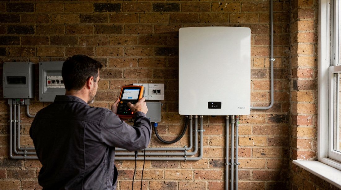
EV charger load management is the control layer that keeps the current drawn by one or more chargers within the capacity of the supply feeding them. On a domestic supply that ceiling is usually the 100A main fuse, and a single 7.4kW charger already takes about 32A of it (EcoHarmony, 2026).
Without control, the charger runs at full output regardless of what the rest of the property is doing. During the evening peak, when the oven, kettle and shower can all be live, that fixed draw is what pushes total current past the fuse rating. Load management watches the whole site and trims the charger first, because the car can wait.
The same principle scales to commercial sites, where the shared limit is the DNO connection rather than a domestic fuse. Whether the supply is one house or a depot, the job is identical: measure total demand, compare it to the ceiling, and hand the charger only the current that is genuinely spare.
The car is the ideal flexible load, which is what makes this work. A vehicle parked overnight does not care whether it charges at full rate for four hours or a lower rate for eight, so trimming the charger during the evening peak costs the driver nothing in practice. Every other circuit in the property expects its power immediately, so the charger is always the right load to give and take.
How does a CT clamp control an EV charger?
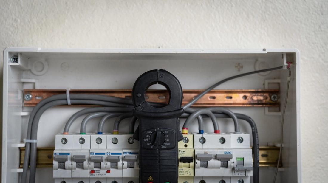
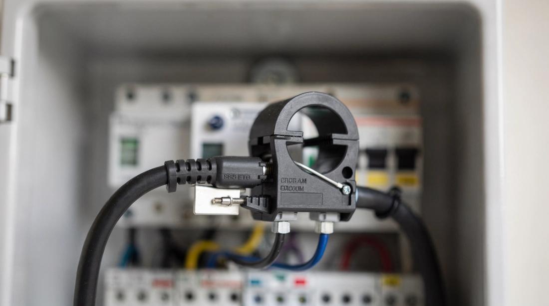
A CT clamp, or current transformer clamp, fits around the incoming live tail and measures total site current so the charger can reduce its rate as demand approaches the main fuse limit. It is the sensor that turns a dumb charger into a load-aware one (Squote, 2026).
Placement decides whether it works. The clamp sits on the meter tails, as close to the meter as possible, so it reads every circuit in the property including the charger's own feed. Fit it downstream of the charger tap and the reading is wrong, which is a common cause of nuisance throttling or a fuse that still trips (Solar Tech Support, 2026).
The physical work is regulated. Fitting a CT clamp on the main fuse tails means working at or just before the meter, which requires isolation and sits under BS 7671. In the field the safe habit is to arrange isolation with the supplier or use an insulated method, never to clamp live tails casually because the fault current there is high.
Some chargers offer alternatives to a hard-wired CT clamp, such as a wireless sensor or a meter that reports total demand over a data link. These ease the install where the meter is far from the charger, but they add a dependency on signal or network reliability. A wired CT clamp remains the most robust choice for a tight supply, because it keeps measuring even when the wireless link drops.
Static versus dynamic load management
Static and dynamic load management both cap the charger, but they differ in whether the cap adjusts. A static limit is a fixed maximum current set at commissioning, while dynamic load management reads live site demand from the CT clamp and raises or lowers the charger output moment to moment (Swift Charging, 2026).
The trade-off is simple to explain to a client:
- Static limit: cheap, no CT clamp, but the charger is throttled all day to a worst-case figure, wasting capacity that is usually free.
- Dynamic limit: needs a CT clamp, but the charger uses whatever current is spare, so cars charge faster overnight when the house is quiet.
- Best fit: static suits a simple single-charger home with plenty of headroom; dynamic suits tight supplies, multiple chargers and commercial sites.
For most modern installs dynamic is the sensible default, because it protects the fuse and still delivers a full charge overnight. The extra cost of the CT clamp is small against the value of not tripping the supply or paying for a fuse upgrade.
How much extra capacity does dynamic load balancing give?
Dynamic load balancing typically frees 30% to 50% more charging capacity inside the same supply than a fixed static limit, because it reclaims the headroom that a worst-case cap throws away (Nuvolt, 2026). On multi-charger sites that difference decides how many bays a supply can carry.
The gain comes from timing. Household and workplace base load is highest for a few hours a day and low for the rest, so a static limit sized for the peak leaves most of the day underused. A dynamic controller pushes the charger up when base load falls, which is exactly when most vehicles are parked and charging anyway.
This is often what avoids a supply upgrade. Before quoting a costly service increase, model the load-managed schedule against measured demand. For export-limited sites the same logic applies to generation, which we cover in the G100 export limitation guide.
Load management on three-phase and commercial supplies
On a three-phase or commercial supply, load management balances chargers across all three phases and against the shared DNO connection rather than a single domestic fuse. The controller allocates spare current per phase, which keeps the site inside its agreed capacity while running as many bays as possible.
Grid engagement shapes the design. Larger commercial charging schemes need a DNO connection and often a G99 application, so the load controller has to respect a capacity that the network operator sets. Read this alongside our G99 application guide, which explains the approval route and timelines.
Commissioning is more involved than a home job. You confirm phase rotation, verify the CT clamps read the right phases, and test that the controller sheds load in the correct order under a simulated peak. Get the phase mapping wrong and the site can trip one phase while two sit idle, which is a frustrating fault to chase after handover.
Phase imbalance is the subtle risk on mixed sites. If single-phase chargers all sit on one phase while the building base load leans on another, the controller can throttle chargers even though two phases have spare current. Spreading single-phase units across the three phases at design stage keeps the balancing headroom usable rather than stranded on the wrong phase.
What do BS 7671 and the Smart Charge Point Regulations require?
Two rulebooks govern a compliant install. BS 7671 18th Edition requires suitable earth-fault protection, and a smart-charger install usually needs a Type B RCD because the electronics can produce smooth DC residual current that a Type A device will not clear (WePowerYourCar, 2026).
The Smart Charge Point Regulations add behaviour rules. Domestic and workplace charge points must default to off-peak charging and apply a randomised delay of up to 600 seconds at the start of a session, so the grid does not see every charger switch on at once (legislation.gov.uk, 2026). The owner can override the delay when needed.
Public and on-street chargepoints sit outside those default-off-peak rules, but the wiring and RCD requirements still apply (GOV.UK, 2026). Record the device settings on the certificate so a later inspector can see the charger was compliant on the day.
Commissioning load management correctly
Commissioning load management well is mostly about proving the sensor and the response. After fitting the CT clamp on the meter tails, load the property or site to a known level and confirm the charger throttles before total current nears the main fuse rating, then release the load and watch it ramp back up.
A few field habits prevent callbacks. Label the CT clamp orientation, record the configured supply limit on the certificate, and test with a real high-current appliance rather than trusting the app reading alone. If you are also quoting the wider job, our EV charger installation cost guide sets out the pricing.
Reonic's installer platform helps here by letting you model the load-managed supply and size the schedule before you are on site, so the CT settings you commission match the design. That single source of truth is what keeps a multi-charger job from drifting between survey and sign-off.
Frequently asked questions
Does every EV charger need load management?
Not every charger, but most benefit. A single charger on a supply with clear headroom can run a simple static limit, yet any tight supply, multiple chargers, or a commercial connection needs active management to protect the main fuse and use spare current efficiently (Swift Charging, 2026).
Where should the CT clamp be fitted?
The CT clamp fits around the incoming live tail on the meter side, as close to the meter as possible, so it measures every circuit including the charger. Fitting it downstream of the charger feed gives a false reading and can cause nuisance throttling or a fuse that still trips under peak load.
Will a 7kW charger overload a 100A supply?
On its own, no, but combined with heavy evening loads it can. A 7.4kW charger draws about 32A, and with a cooker, shower and kettle live the total can approach the 100A fuse rating, which is exactly why load management trims the charger first during the peak.
Do I need a Type B RCD for a smart charger?
Usually yes. A smart-charger install generally needs Type B RCD protection to meet BS 7671, because the charger electronics can produce smooth DC residual current that a Type A device cannot detect and clear. Some chargers include equivalent protection, so check the manufacturer's declared specification.
What is the randomised delay on EV chargers?
It is a regulatory feature. Domestic and workplace charge points must default to off-peak charging and apply a random delay of up to 600 seconds at the start of a session, spreading grid demand so chargers do not all switch on together. The owner can cancel the delay when an immediate charge is needed.