
CT clamp installation for solar is the small wiring step that decides whether export limitation, consumption monitoring and hybrid inverter control actually work on site. With UK deployed solar reaching 21.8 GW across 1,951,000 installations by the end of January 2026 (pv magazine, 2026), more systems than ever depend on a correctly fitted current transformer to stay inside their Distribution Network Operator export limit.
A CT clamp, short for current transformer, reads the current passing through a cable and sends that signal to an inverter or energy meter. Fit it on the wrong conductor, or point the arrow the wrong way, and the reading flips, so the system either over exports or throttles a healthy array toward zero. This guide covers where the clamp sits, how to wire it, and how it ties into G98, G99 and G100 compliance.
Key Takeaways
- A CT clamp measures current at the origin of supply so the inverter knows how much power the property imports or exports.
- Export limitation under G100 depends entirely on the CT reading, which is why DNOs accept it in place of a bigger G99 connection.
- The clamp must sit on the correct cable, usually the main incoming line conductor, with its direction arrow facing the grid.
- A reversed or mis placed CT is the single most common cause of a system that exports nothing or trips its limit.
- Always verify the reading with a known load before you leave, not with the display at idle.
What is a CT clamp, and why does a solar install need one?
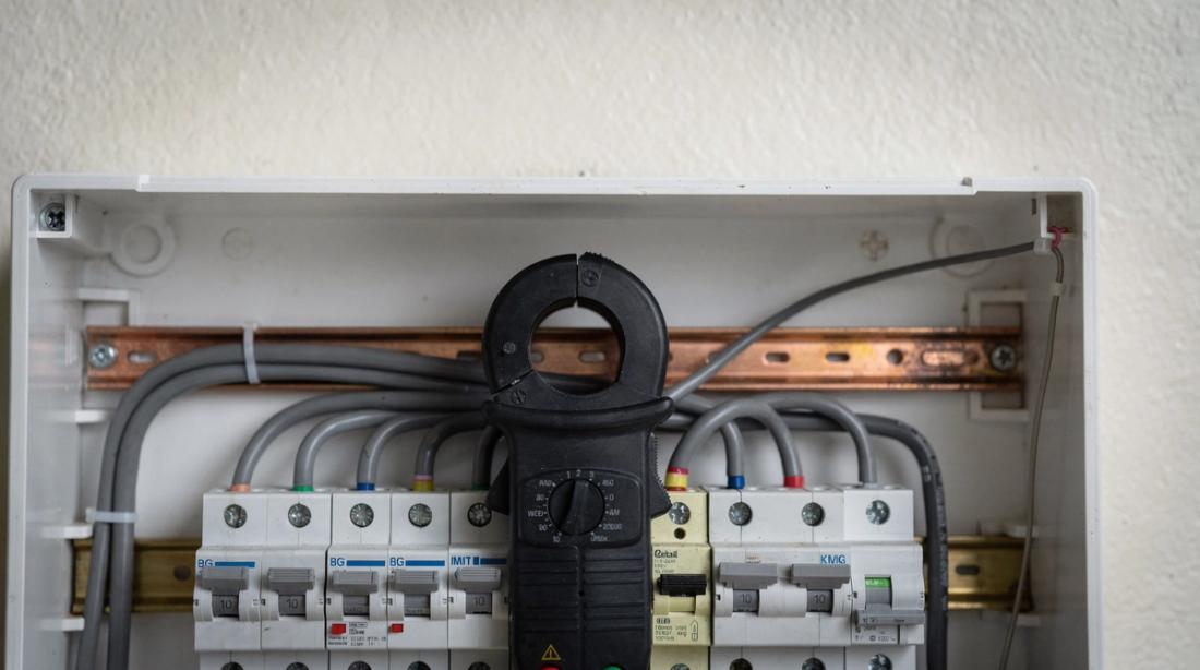
A CT clamp is a split core current transformer that clips around a live conductor and outputs a small signal proportional to the current flowing through it. A solar install needs one whenever the inverter has to know real time import or export, which covers export limitation, zero export, time of use battery control and consumption monitoring. Without it the inverter runs blind.
The clamp does not break the circuit, so you fit it without isolating the tails at the cut out, though you still work to safe isolation practice on everything you do open. Because UK domestic systems make up around 30% of deployed solar capacity (pv magazine, 2026), most of these clamps go into tight domestic consumer unit spaces where neat routing matters.
CT clamp versus current transformer: same device, different names
On a solar job the terms CT clamp, current transformer and CT coil all describe the same component. Manufacturers print current transformer on the datasheet and installers say CT clamp on site. The important number is the ratio, for example 100A to 50mA, because the inverter firmware expects a specific ratio and gets its scaling wrong if you fit a mismatched part.
Split core clamps open on a hinge so they wrap an existing cable, which is what makes a current transformer solar install quick on a retrofit. Solid core versions give slightly better accuracy but need the cable threaded through them, so they suit new tails only. For most retrofits the split core clamp is the practical choice.
Accuracy class also varies. A class 1 current transformer reads within about one percent, which is ample for export limitation and monitoring, while a cheaper unclassed clamp drifts further and can make a tight export cap look breached when it is not. On any site where the DNO sets a firm limit, a known accuracy class is worth the small extra cost at the wholesaler.
Where to fit a CT clamp on a solar system
The CT clamp belongs at the origin of supply, on the main incoming line conductor between the meter and the first point of the installation, so it sees every amp the property imports or exports. Export power management under G100 relies on this placement, because the manager can only limit export to the value the DNO permits if it measures the true net flow at the boundary.
Fit the clamp after the meter tails split for any sub main, not before, or it will miss part of the load. On a three phase supply you fit one clamp per phase and match each to the correct inverter input. Getting the phase pairing right is as important as the direction, since a crossed phase reads power that belongs to another leg.
How to fit a CT clamp, step by step
Plan the route first, then follow a repeatable sequence. The clamp carries a low voltage signal, but the conductor it clips is live, so treat the work with full respect for the incoming supply.
- Identify the main line conductor at the origin of supply and confirm it carries the whole load.
- Open the split core clamp and place it around that single conductor, never around line and neutral together.
- Point the direction arrow, often marked K to L or an arrow toward the load, the way the manufacturer specifies for grid flow.
- Close the clamp fully until it clicks so the core halves meet with no gap.
- Route the signal cable away from the mains tails to avoid interference, and keep any extension within the rated length.
- Terminate at the inverter or meter CT input, observing polarity on the two signal cores.
A field note from retrofit work: label the CT lead at both ends before you tuck it into a busy consumer unit, because tracing an unlabelled signal pair six months later during a fault call costs far more time than the label ever did.
Fit the clamp before you energise the array, then power up and watch the reading settle. A CT added after the inverter has already learned a zero baseline sometimes needs a firmware restart to pick up the new feed, so fitting first often saves a second trip up the loft ladder.
How do you wire a CT clamp to the inverter?
The CT clamp inverter connection is a two core signal pair into a dedicated CT terminal, not a power connection. Polarity matters, so the core marked as the start goes to the terminal the manual names first. Many hybrid inverters show a live power reading once wired, which lets you confirm direction before the system runs. A hybrid inverter needs this feed to manage charge, export and backup correctly.
If the inverter sits far from the meter, use the manufacturer approved extension and keep within the stated maximum, because an over long or thin signal run drops the reading and makes export limitation inaccurate. For deeper sizing and compliance detail, the hybrid inverter guide walks through matching the meter and inverter together.
Some inverters have no CT input and expect a separate energy meter on the DIN rail instead. The CT clamp then wires into that meter, and the meter talks to the inverter over RS485 or Modbus. The principle holds either way, because the clamp still sits at the origin of supply and still needs the correct direction, only the signal now passes through the meter before it reaches the inverter.
Do you need a CT clamp for export limitation?
Yes, export limitation cannot work without current measurement, and the CT clamp provides it. Under G98 you can connect up to 3.68kW per phase, equal to 16A per phase, and simply notify the DNO within 28 days (selectra, 2026). Above that you move to G99 and need approval before you connect, which is where export limitation earns its place.
By fitting a larger array and capping export with a CT fed limiter, an installer can keep a project in the faster G98 lane while still serving the home (selectra, 2026). Where the DNO sets a firm export cap, G100 export power management must bring export back within the limit within one minute for residential sites and three minutes for commercial ones (alternergy, 2026). The G100 export limitation guide sets out the full scheme, and the routes split between the G98 notification and G99 approval processes.
Common CT clamp mistakes that break export limitation
Most CT faults come down to four errors, and all four produce a system that behaves strangely rather than failing outright. A reversed clamp reads export as import, so a zero export site pushes power it should hold back. A clamp on the wrong cable misses part of the load, so the limiter under reads and the DNO cap is breached.
The other two are a loose core that never fully closes, which gives a weak and noisy reading, and a signal lead run alongside the mains, which injects interference. Each one passes a quick glance at the display, which is why verification with a real load is the only reliable check. Export income through the Smart Export Guarantee, which paid generators £30,749,485 in its fourth year, a 327% rise year on year (Solar Power Portal, 2025), depends on that export reading being right.
Verification takes two minutes. Switch on a known load, read the direction and rough magnitude, then switch it off and watch the reading fall back. If the number climbs when it should drop, the clamp is reversed, and a firmware polarity flip or a physical turn of the clamp fixes it on the spot before anyone leaves site.
What CT clamp specification should you choose?
Match the clamp to the supply and the inverter, not to the panel count. The current rating must cover the full load current at the origin of supply, the ratio must match the inverter firmware, and the aperture must fit the tail you are clipping. The table below sets out the usual decision points.
- Current rating: Typical domestic choice: 100A split core. Why it matters: Covers a standard single phase domestic main without saturating.
- Ratio: Typical domestic choice: As specified by inverter. Why it matters: Wrong ratio scales every reading incorrectly.
- Core type: Typical domestic choice: Split core. Why it matters: Clips an existing tail without disconnection on a retrofit.
- Aperture: Typical domestic choice: 16mm or larger. Why it matters: Must close fully around 25mm tails.
- Lead length: Typical domestic choice: Within rated maximum. Why it matters: Over long runs drop the signal and skew export control.
Treat the Smart Export Guarantee, now offered through a scheme Ofgem reports on each year (Ofgem, 2025), as the reason precision pays: a home only earns on what the CT records as exported. Before the install, a thorough site survey confirms where the origin of supply sits and whether the clamp will fit the available space.
Aperture is the detail installers overlook most. A 16mm clamp will not close around 25mm meter tails, and forcing it leaves a gap that ruins the reading, so measure the tail before you order and keep a larger clamp in the van for the heavier supplies on older properties.
On monitoring, our own platform reads that CT feed back as live import and export data, which is useful when you want to prove a limit holds without a return visit.
FAQ
Where exactly does the CT clamp go on a domestic solar install?
It clips around the main incoming line conductor at the origin of supply, between the meter and the consumer unit, so it measures the whole property load. Place it after any sub main split, not before, and keep it on the line conductor alone, never around line and neutral together.
Which way should the CT clamp arrow face?
The direction arrow, often marked K to L, follows the manufacturer rule for grid flow, usually pointing toward the grid or the load as the manual states. A reversed arrow makes the inverter read import as export, so a quick live load test before you leave confirms the direction is right.
Can one CT clamp handle a three phase supply?
No, a three phase supply needs one clamp per phase, each matched to the correct inverter input. Crossing the phases makes the inverter read power from the wrong leg, which breaks export limitation and consumption monitoring. Label each lead by phase during install to avoid confusion at commissioning.
Do I need a CT clamp if I am not export limiting?
Only if the inverter needs to know import or export for battery control, zero export or consumption monitoring. A simple grid tied array with no limit and no battery can run without one, but most modern hybrid systems use the CT feed, so fitting it is usually worthwhile.
How do I test the CT clamp is working?
Apply a known load, such as a kettle, and watch the inverter or meter reading move by roughly the expected amount in the correct direction. An idle display can look fine while the clamp is reversed or loose, so a real load test is the only check that proves the reading and its direction.