
Roof solar panel mounting structure design now carries a legal paper trail in the UK. MIS 3002 V6.0 is mandatory for all MCS submissions from 18 June 2026. It requires documented wind load evidence, not just a written confirmation from the installer (Solar Surveys, 2026). That single change turns mounting design into a structural engineering exercise, one with a paper trail an assessor, lender, or insurer can check.
For installers used to relying on a manufacturer datasheet, the shift matters. Across 575 UK commercial rooftops assessed for solar feasibility, one in three needed structural intervention before panels could go on (PBC Today, 2026). This guide sets out how wind uplift, roof load-bearing capacity, and structural survey evidence fit together, so a mounting design satisfies MCS 012 and MIS 3002, not just the fixing schedule.
Key takeaways
- MIS 3002 V6.0, mandatory from 18 June 2026, requires documented wind load calculations to BS EN 1991-1-4, not a written sign-off alone.
- MCS 012 Issue 3.0 sets a Maximum Design Wind Uplift Resistance for mounting products, tested with partial safety factors between 1.1 and 1.44 depending on failure mode.
- Section 5.9.6 of MIS 3002 lists seven roof configurations, including hipped, valley, and sub-30-degree pitch roofs, that make a qualified structural engineer mandatory.
- Flat roof ballasted systems always require engineer sign-off under Section 5.9.13(h); there is no discretion on this point.
- A structural assessment should treat dead load, wind uplift, and snow load as three separate cases, never combined into a single number.
What Counts as Wind Load Evidence Under MCS 012 and MIS 3002?
Evidence means a documented wind load calculation referenced to BS EN 1991-1-4. It has to be produced or reviewed by a suitably competent person, not just a manufacturer's software output. Under MIS 3002 V6.0, software-generated assessments that have not been reviewed and signed by a qualified structural engineer do not satisfy the requirement (Solar Surveys, 2026).
MCS 012 Issue 3.0 was published on 10 May 2023. It became mandatory for newly certified mounting products from 10 May 2025 (MCS, 2023). The standard sets out how a mounting system or component is tested for wind uplift, fire, and weathertightness. It then declares a Maximum Design Wind Uplift Resistance, in kilopascals for systems or kilonewtons for individual components.
The two standards work together rather than duplicating each other. MCS 012 tests and certifies the product. MIS 3002 tells the installer how to prove, on a specific roof, that the calculated wind load stays within that declared resistance. Confusing the two is a common reason installers submit incomplete evidence to a certification body. For background on how the wider scheme fits together, see Reonic's guide to MCS accreditation.
How Do You Calculate Wind Uplift on a Roof-Mounted Solar Array?
Wind uplift is calculated using BRE Digest 489's formula, F = qp x Cp,net x Ca x Ct x Aref. It combines site wind pressure with pressure coefficients that depend on the array's position on the roof (Construction Cost, 2025). In exposed Scottish or coastal locations, this can produce negative pressure of 1.5 to 2.5 kN per square metre on a tilted array (Solar Surveys, 2026).
The basic wind speed input comes from BS EN 1991-1-4's UK National Annex, read off a postcode-specific map. It is then adjusted for altitude, terrain roughness, and building height. MCS 012 also references the IEC Code of Practice for Grid Connected Solar PV Systems. It requires a partial factor of 1.35 on the calculated wind load, applied before comparing it against the mounting system's declared resistance (MCS, 2023).
Wind uplift, dead load, and snow load must be assessed as three separate load cases. Uplift acts upward and is only partly offset by the panel's own weight. It is never simply netted off against the gravity case, because the two act in opposite directions at different times. Getting this sequencing wrong is one of the most common errors in self-produced calculations.
What Roof Load-Bearing Capacity Do You Need for Solar Panels?
A typical panel, rail, and fixing combination adds roughly 15 to 20 kilograms per square metre of dead load. Most modern pitched residential roofs can absorb this without reinforcement (Castle Surveys, 2025). Older structures and non-standard roof coverings are a different story, and this is where load-bearing capacity checks earn their keep.
Ageing asbestos-cement roofs are a recurring failure point. Sixty-two percent of them failed a wind-uplift adequacy check in one recent sample of commercial assessments (PBC Today, 2026). Corrosion, section loss in metal sheeting, and prior alterations to purlins or rafters all reduce the margin a designer can assume is there.
Under Building Regulations Approved Document A, any addition affecting structural integrity needs a proper assessment. That assessment has to consider the roof as it actually is, not as the original drawings say it should be.
When Do You Need a Structural Survey Before Installing Solar Panels?
Section 5.9.6 of MIS 3002 V6.0 mandates a qualified structural engineer for seven specific roof configurations, regardless of system size (Solar Surveys, 2026). Outside those triggers, a suitably competent installer can often carry out the structural check on a simple, standard domestic roof.
The seven triggers are:
- Hipped roofs
- Valley roofs
- Asymmetric duo-pitched roofs
- Dormers
- Parapets
- Roofs with a pitch below 30 degrees
- Any roof showing signs of structural distress
Flat roof ballasted systems sit outside this list, because they carry their own absolute requirement, covered below. On commercial and industrial roofs, these triggers come up often. In one dataset, 78% of flat-roof ballasted installations needed their ballast reconfigured to pass a combined load check (PBC Today, 2026). For roof-covering-specific fixing detail, see Reonic's guide to solar panels on a slate roof.
Which Solar PV Wind Load Calculators and Tools Do Installers Use?
Installers commonly use spreadsheet or web-based wind load calculators built to BS EN 1991-1-4 and BRE Digest 489. One UK-specific example is the tool from Solar Calculator HQ (2025). It gives an early read on whether a design is close to a mounting system's declared limit. They are useful for triage, not for final sign-off once a project falls under one of the MIS 3002 structural engineer triggers.
In practice, a quick spreadsheet check on site is often enough to flag whether a job needs escalating. Running the postcode's basic wind speed and roof pitch through a calculator, before committing to a mounting system, tends to save a redesign later. That holds even on jobs that will not ultimately need an engineer's signature. Where the numbers sit close to the declared Maximum Design Wind Uplift Resistance, that is the trigger point. Commission a signed structural report rather than rely on the calculator output alone.
Mounting Structure Design Choices That Affect Wind and Structural Loading
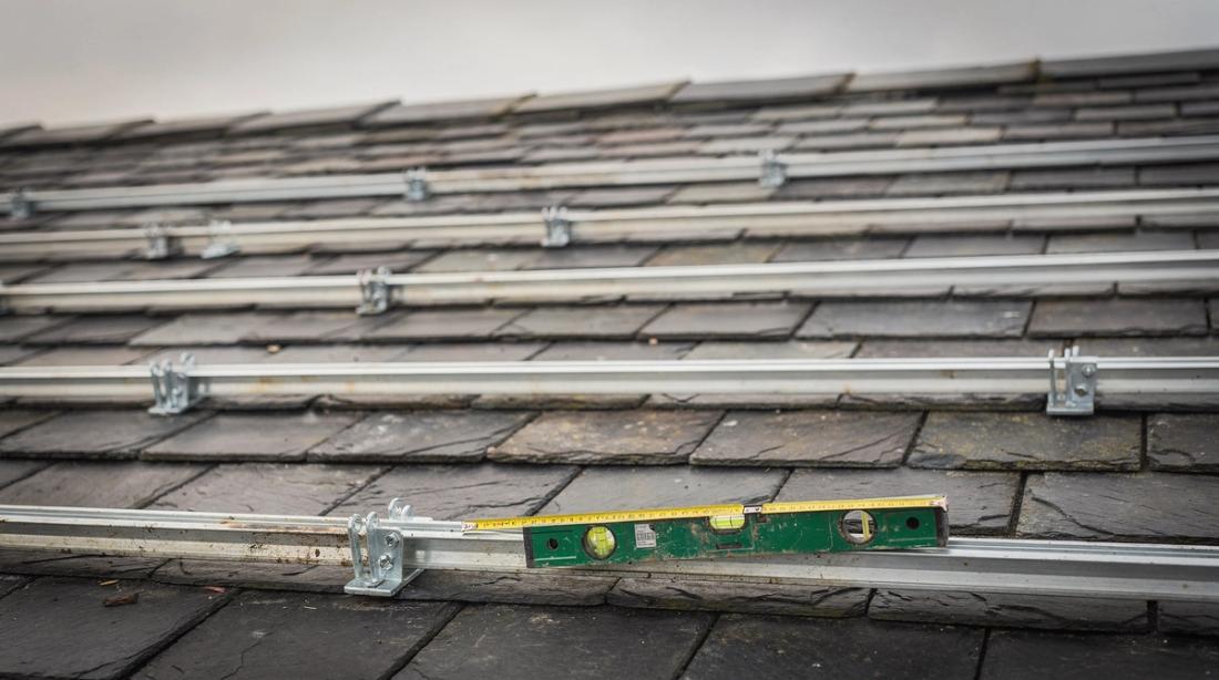
Rail spacing, fixing density, and the choice between mechanically attached and ballasted systems all change how much wind load a roof structure has to carry. A mounting system with closer rail centres and more fixings per panel spreads the same wind uplift across more connection points. That reduces the load at each one.
BS EN 1991-1-4 does not treat a roof as uniformly loaded. It defines pressure zones, so that corner and edge areas of a flat roof see far higher suction than the centre of the array.
- Zone F (Corner areas): 2 to 3 times the internal zone pressure
- Zone G (Edge strips along roof length and width): 1.5 to 2 times the internal zone pressure
- Internal zone (Central area of the array): Baseline pressure
Designers who spread panels evenly across a roof, without accounting for these zones, routinely under-specify fixings at the corners. Non-mechanically attached ballasted systems work differently. They rely on a default coefficient of friction of 0.3, declared under MCS 012, unless a manufacturer has tested a higher value on a specific substrate (MCS, 2023). For a comparison of mounting approaches by roof type, see Reonic's in-roof versus on-roof solar panels guide.
Flat Roof Ballasted Systems: A Special Structural Case
Flat roof ballasted arrays always require a qualified structural engineer under MIS 3002 V6.0 Section 5.9.13(h). There is no discretion for smaller domestic-scale systems (Solar Surveys, 2026). The engineer has to assess the combined imposed load from panels, mounting frame, and ballast blocks against the existing structure's capacity.
Ballast has to resist both uplift and sliding. MCS 012 testing establishes the Maximum Design Wind Uplift Resistance of the ballast system itself. It then separately checks resistance to sliding, using the 0.3 coefficient of friction or a tested alternative, unless the array is mechanically tethered.
Where these numbers do not stack up, the fix is usually more ballast, better distribution, or mechanical restraint at the perimeter. Any of those changes adds weight the original roof loading assessment needs to account for. Reonic's guide to solar panels on a flat roof covers the mounting hardware side of this in more depth.
Building a Compliant Structural Evidence Package: Step-by-Step
A compliant evidence package starts with site data and ends with a signed report. That report is what a certification body, lender, or insurer can rely on for the life of the installation. Skipping steps here is the most common reason a job stalls at MCS sign-off.
- Gather roof drawings, construction type, age, and any known defects or prior alterations.
- Determine the site's basic wind speed from BS EN 1991-1-4's UK National Annex, adjusted for altitude and terrain.
- Check whether the roof configuration or system type triggers a mandatory structural engineer under Section 5.9.6 or 5.9.13(h).
- Confirm the chosen mounting system's declared Maximum Design Wind Uplift Resistance under MCS 012.
- Commission a desktop or on-site structural survey where triggers apply, and keep the signed report with the job file.
- Retain wind load calculations, the survey, and the MCS 012 product certificate together for audit.
Roofing work remains one of the higher-risk parts of any installation programme. Falls from a height were the single largest cause of workplace fatalities in Great Britain in 2025/26, with 31 deaths out of 126 workers killed overall (HSE, 2026). A properly sequenced structural evidence process, done before anyone goes on the roof, is as much a safety control as a paperwork exercise.
Weather-related property claims reached roughly £1.6 billion in the UK in 2025, a quarter of all property insurance claims that year (The Cool Down, 2025). A mounting design backed by proper wind load evidence gives a building owner something concrete to point to. If an insurer ever asks how the roof was assessed, that evidence is the answer.
Some installers now keep this evidence alongside their design files, in software such as Reonic's platform. The wind load calculation, the survey report, and the MCS 012 declaration then sit together, rather than in separate folders when an audit or a claim comes in.
Frequently Asked Questions
Does every solar panel installation need a wind load calculation?
Yes, in the sense that every installation needs to show the mounting system's declared resistance is not exceeded on that roof. The depth of evidence varies. A simple domestic pitched roof may only need a competent installer's documented check, while a Section 5.9.6 trigger or any flat roof ballasted system needs a qualified structural engineer's signed calculation.
What is the difference between MCS 012 and MIS 3002?
MCS 012 is a product standard. It certifies mounting systems and components through wind uplift, fire, and weathertightness testing, and declares a Maximum Design Wind Uplift Resistance. MIS 3002 is the installation standard. It tells installers how to prove, for a given site and roof, that the calculated wind load stays within the certified product's declared limit.
How long does a structural survey for solar panels take?
Desktop structural roof loading reports, based on drawings and site photographs, are typically delivered against a 48-hour benchmark by specialist providers (Solar Surveys, 2026). An on-site survey is needed where drawings are missing or the roof is more complex. These generally take longer to mobilise, often with a 24-hour callout target followed by a few days for the written report.
Can manufacturer design software alone prove wind uplift resistance?
No. Under MIS 3002 V6.0, outputs from solar design software, including array layout tools and manufacturer mounting calculators, do not satisfy the documented evidence requirement alone, even where they include load figures. Only a report produced, or reviewed and signed, by a suitably qualified structural engineer meets the standard where one is required.
What happens if a roof fails a structural check for solar panels?
The usual outcomes are a revised mounting design with more fixings or a different bracket type, reinforcement of the existing structure, a reduced array size, or moving panels away from high-uplift corner and edge zones. In some cases, particularly ageing asbestos-cement or corroded metal roofs, remedial roofing work has to happen before an installation can proceed at all.